Tag Archives: QHY268C

A step by step guide to Collimation

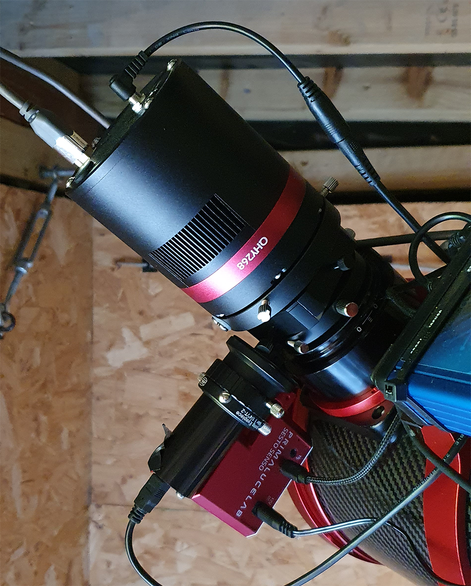
If like me you own some sort of reflector telescope, whether this be a Newtonian, Dobsonian, Ritchey Chretien or as I have a Hyperboloid Astrograph then you’ll know that there is a very strong importance on collimation, the faster the optics the more critical collimation becomes, especially for imaging. After recently removing the rear mirror assembly for cleaning, as well as changing from the QHY183M to the QHY268C-PH amongst onther stuff in the imaging train, I wanted to share my experience and knowledge around collimation. Let’s start off with the details on what I use

Part 1 – Aligning the Secondary Mirror with the Focuser

Now on my SharpStar 15028HNT, they recommend you unscrew and remove the corrector from the focuser, however I have found no difference in collimation with or without the corrector in place and because it is part of the optical train I’d rather include it in the collimation, so the first step for me since my primary mirror was currently removed was to check the secondary alignment with the focuser, as well as the rotation of the secondary in relation to the focuser, in order to do this, I use the Teleskop-Service Concenter eyepiece, the eyepiece itself has a set of rings engraved into the plastic apperture like so

Teleskop-Express Concenter Eyepiece markings on lower end of barrel

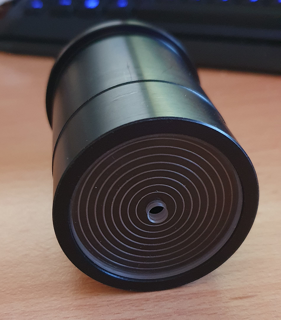
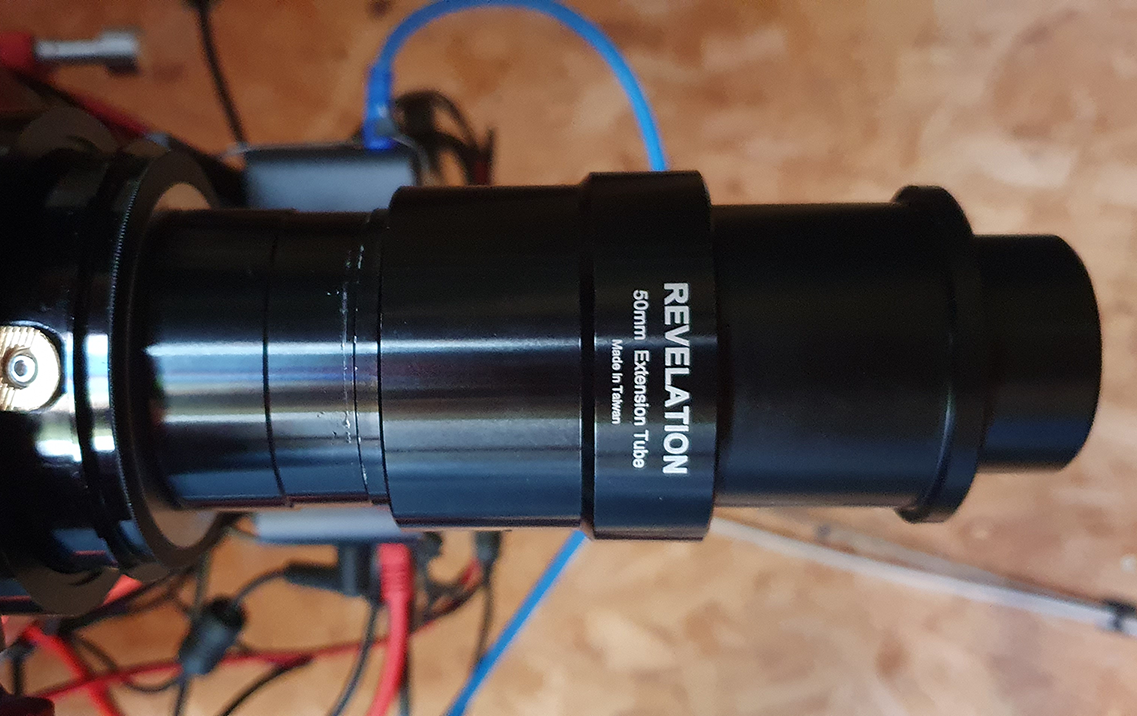
I ensure that my focuser is at the most inward position and since my SharpStar has an M48 thread on the focuser, I used a 2″ extension tube that has an M48 thread on it, and placed the concenter eyepiece in there:

M48 threaded 2″ Extension tube with Teleskop-Express Concenter Eyepiece

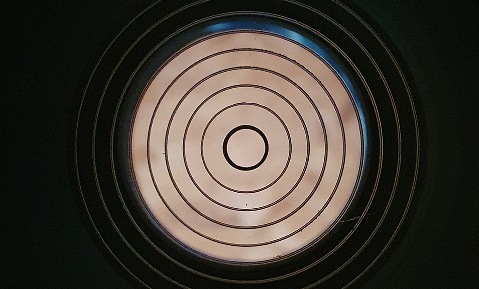
This serves well to get the rotation and alignment of the secondary with the focuser by ensuring that the mirror appears as a perfect circle between the rings, now you can adjust your focuser position in order to get the edge of the mirror to appear on the lines, this is what the view looks like through the concenter eyepiece:

Here you can see the secondary mirror appears circular and in line with the concenter eyepiece markings showing a successful alignment with the focuser

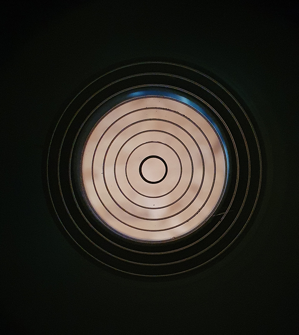
The blue at the top right of the image is a piece of card I stuck behind the secondary in order to show the edge of the mirror better.

As you can see my secondary mirror is pretty much perfectly aligned with the focuser and square with the focuser also, if your mirror shows up as more eliptical, this means the mirror needs to be rotated, if the mirror does not fit in within the circle itself, for example if it is over to the left or right, you will need to move the mirror forward or backwards by means of loosening or tightening the central screw that holds the secondary.

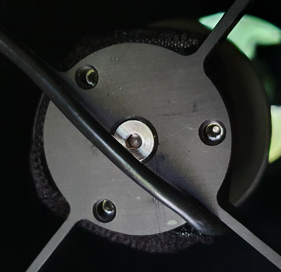
You can see from the following image, I have a central screw which is used for moving the mirror up or down the tube away from or closer to the primary, as well as rotation of the mirror, but then there is also the three collimation screws that are used to adjust the mirror direction itself which we will talk about in the next section

Here you can see the central adjustment screw for adjusting the mirror rotation and centering the mirror with the focuser, the three outer scres are used for adjusting the tilt of the mirror to align with the primary

Part 2 – Aligning the Secondary Mirror with Primary Mirror

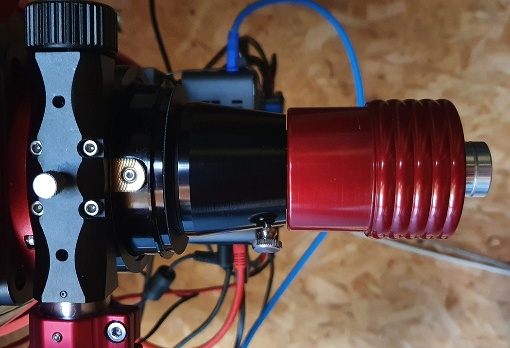
Now that we have our secondary mirror lined up and square with the focuser, the next step is to align the secondary with the primary, now for this I will use my FarPoint Astro Laser collimator, which itself has recently been collimated by FarPoint Astro, now you can re-use use the 2″ extension tube and place the laser into the tube, but for the SharpStar I will use the M48 to 1.25″ lockable adapter like so:

FarPoint Astro laser collmator in the SharpStar M48 to 1.25″ Adapter

Now the point of this part is to ensure that the laser hits the centre spot of the primary mirror, if it does not, then this is where you would adjust one or more of the three screws on the secondary, as you undo one, you should tighten the other two, as you can see from this image, I need not make any adjustments as the laser hits the centre of the primary perfectly:

Here you can see that the laser hits the primary mirror centre spot

Part 3 – Aligning the Primary Mirror

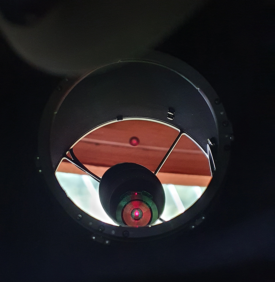
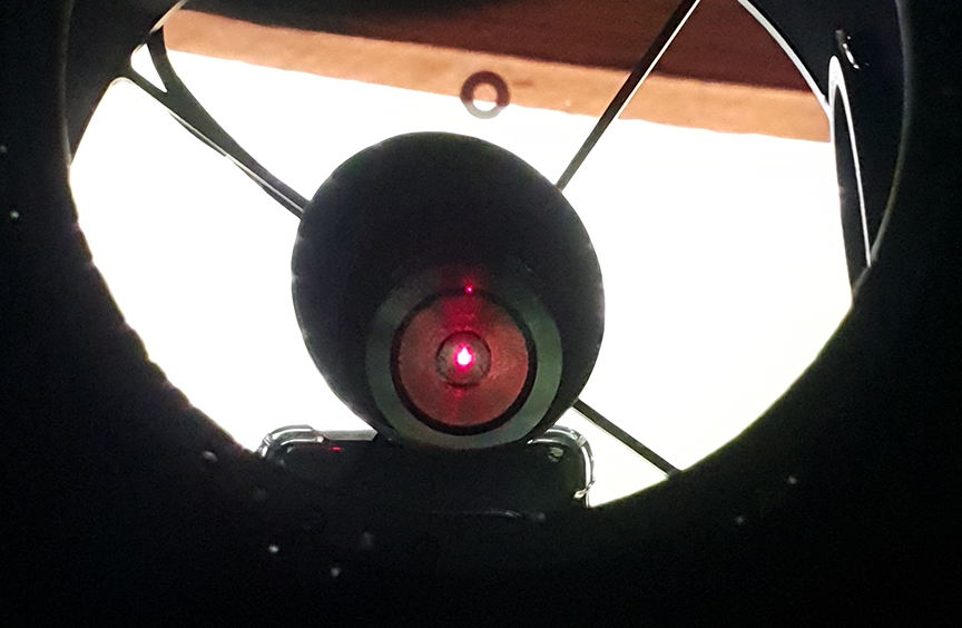
Now since I do not have to make any further adjustments to the secondary mirror, it is time to focus on the primary mirror, the trick here is to get the laser beam to return to the point of origin, here’s an example of the primary not being correctly aligned:

You can see two dots here, one is the laser aperture, the other is the reflection of the laser from the primary mirror, this reflection needs to meet the aperture

You can clearly see the red dot to the top left of the laser apperture, this means that the primary needs some adjustment by means of the three collimation screws which are situated on the rear of the primary mirror assembly:

Here you can see the primary mirror collimation screws, the larger push/pull the mirror, the smaller are locking screws to secure the mirror in place after successfully collimating.

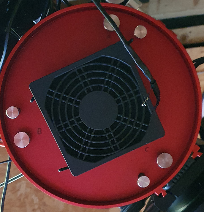
Most telescopes have a push – pull method here, turning anti-clockwise will push the mirror further up the tube, whereas turning clockwise will pull the mirror towards the bottom of the tube, it is very important not to keep turning anti-clockwise because this could result in the screws becoming disconnected from the primary mirror. After an adjustment on a couple of the collimation screws, my primary is now aligned properly as the laser beam returns into the laser apperture:

Here you can see that there is no additional dot, the dot is centered right on the laser aperture indicating primary alignment is complete

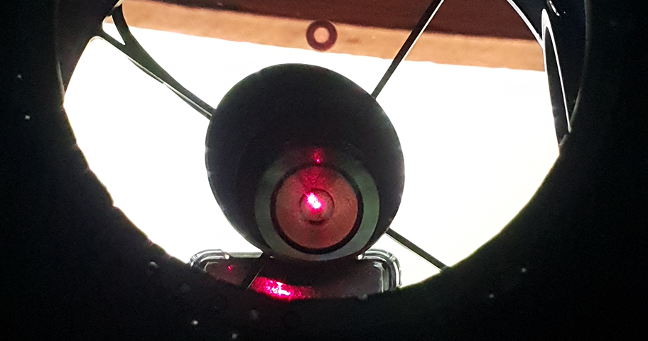
Once the laser collimation has been completed, it is easy to verify this with the FarPoint Auto-Collimator, the eyepiece has a mirror inside which allows you to see where the centre spot of the mirror is and will form a slightly pale dot in the middle, if the dot appears in the middle then you have your collimation pretty much spot on after following the above, maybe a very slight adjustment on the primary collmation screws is all that is required, you can see here what the view looks like:

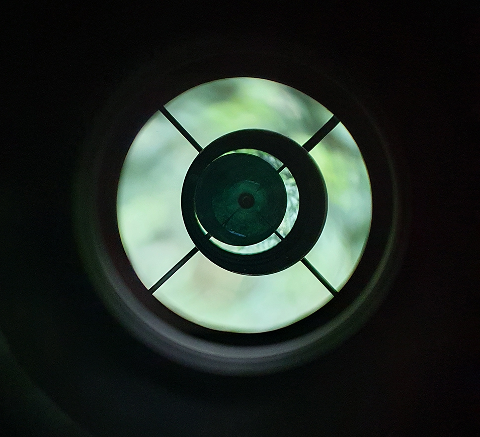
It is also normal on faster telescopes to see the mirror appearing offset as opposed to central to the OTA itself. Once completed, I would typically then perform a star field test and I prefer to use the Multi Star Collimation in CCD Inspector for this, you can of course use the de-focused star method.

I hope you found this useful, I just thought I would share my process in performing collmation to help others who may be on that journey also.

QHY268C APS-C Colour Camera Review – Part 1

As many of you know, I have been using QHY cameras for a while, but with my plan to move to a RASA telescope next year and wanting to image with a bigger sensor than the QHY183M I decided to go for a bigger sensor but moving away from Mono, the latest addition to the QHY familly is the QHY268C Photographic Version. I had been talking to the QHY team for a long time about this particular camera, and finally I have one.

The QHY268C is a once shot colour camera based on the APS-C Sized back illimunated Sony IMX571 sensor, the camera has a true 16-Bit Analog to Digital Convertor (ADC), now there are a few camera models out there using this sensor, cameras such as the ZWO ASI2600, but one thing that sets the QHY268C apart from the others is the ability to have a 75ke full well capacity which is 25ke higher than the ZWO ASI2600. In my opinion, when imaging at fast focal ratios, a higher full well is desired to protect the colour around bright stars for example.

Opening the box I was greeted with a camera that was bigger and heavier than my 183M, but then the sensor is much bigger than the 183M anyway so this would be expected, but what I did not expect is the additional items that came with the camera:

Inside the box was:

  • QHY268C Photographic Version
  • UK mains plug for 12V AC adapter
  • 12V AC adapter
  • Car 12v power cable
  • Self locking power cable
  • 1.5M USB 3.0 cable
  • Dessicant drying tube
  • Self centering adapter plate
  • M54 to M48 adapter plate
  • M54 to 2″ nose adapter
  • A range of spacers to give you from 0.5mm to 13.5mm spacing
  • Associated screws for spacing adapters

QHY cameras have come along way since I bought my QHY183M, one of the things QHY has really worked on is amp glow, my early version of the QHY183M was renowned for was amp glow, which could be removed in image calibrations, but the QHY268C produces no amp glow whatsoever, below is a dark frame of 600S taken at -13.5C and you can clearly see there is no evidence of amp glow.

Single frame 600 seconds, Gain 26, Offset 30, -13.5C – Mono (Not Debayered)

Attaching to the telescope was pretty straight forward as I had already planned the imaging train before the camera arrived, since I will be using the SharpStar 15028HNT F2.8 Paraboloid Astrograph which has an M48 thread, I decided to keep the whole imaging train at M48 except for the camera of course which has an M54 thread, so I did not actually need to use any of the adapters that came with the camera, the reason for this is because I wanted to include a filter drawer, so my image train consists of the following (from telescope to camera)

  • TSOAG9 – TS Off Axis Guider (9mm)
  • TSOAG9-M48 – TS M48 Adapter for the OAG (2.5mm)
  • TSFSLM48 – TS 2″ Filter Drawer with M48 Thread (18mm)
  • M48AbstimmA05 – TS Optics 0.5mm Aluminium spacing ring (0.5mm)
  • TSM54a-m48i – TS M48 to M54 Adapter (1.5mm)
  • QHY268C with M54 Centering Adapter (23.5mm)

As you can see with all the above I reach my desired back focus of 55mm perfectly, if I was not going to be using a filter drawer (For my Optolong L-Pro and L-eXtreme filters), I would probably have stuck with the spacers that came with the camera. Below is a picture of the camera successfully connected to the telescope.

As far as settings go, after speaking with QHY on this at great length, I will be imaging in Mode 0 (Photographic mode) to avail of the massive 75ke full well, offset I will leave at 30, but Gain I will use two different settings, I will use Gain 0 for most bright objects with the L-Pro filter, but for the L-eXtreme, I’ll probably set a gain level of 26, luckily with SGPro I can set the gain level per object. From a cooling perspective I always image at -20C, one thing I have noticed is that this camera cools to exactly -35C below ambient, I tested this when the ambient temperature was 20.10 degrees, and the camera cooled down to -14.9C, it was always 25C lower until the ambient dropped below 15C and the camera remained at my setting of -20C.

The build quality of the camera is as expected having owned a QHY183M, one thing I did notice is that the fan in the QHY268C is much quieter than the 183M. Technical Details of the camera:

CameraQHY268CQHY183M
Image SensorSony IMX571Sony IMX183
Sensor SizeAPS-C1″
IlluminationBack IlluminatedBack Illuminated
Pixel Size3.76um2.4um
Effective Image26mpx20mpx
Full well capacity51ke
(75ke in extended mode)
15.5ke
ADC16-Bit12-Bit
Image Buffer Memory1GB/2GB128MB
Max Cooling Delta-35C-40C
Weight1006g650g

I can’t wait to get imaging with this camera, I have a very aggresive target list for this year in both RGB and Narrowband with the Optolong L-eXtreme filter, I will write part two of the review once I have some actual imaging data. Time to build my dark library.